|
  |
I want to point out that this page will explain how you can re-build any of my fighters. However, my fighters are continually changing and growing and so pictures throughout the rest of the site may or may not show this progression and I'll only be adding design notes here for additions to my fighters that function fully.
Back Ground:![]()
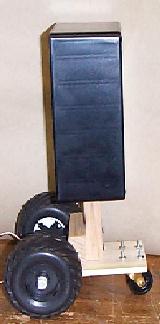
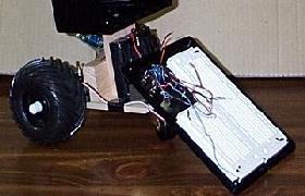
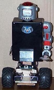
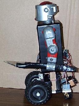
The picture to the left is the front of Sir Sagramore who now has an updated head (not
shown). The picture to the right is a side view showing the back of the Basic Stamp
and his arm for interchangeable weapons. As you can see from the pictures my
bots lean a bit towards the front. With the placement of other components my
bots stay pretty level, but in my current upgrades to Sagramore I have modified his
trailing wheel so it does not make him lean forward. You may notice the placement of
batteries in the back (4-AA and 2-9 volts). My Basic Stamp and switches are attached
to the lid of the project box.
You may notice two other features, an IR sensor placed right below the project box (from the front view) and my contact sensor shut off swtich right above it placed at the 6 inch mark. To the left side you also see the second motor shut off sensor place at the 6 inch mark on the robots side (from front view also). My bot's IR sensor kit allows it to look for other fighters and detect when something is too close to it's own contact sensor. Also from the front at the bottom in between the wheels you might notice my IR sensors I built for line detection so they know where the edges of the ring are. There is a Right and Left IR sensor and LED pair.
As you can see the body is constructed of wood and a project box from Radio Shack. This design makes them robust enough to carry out many functions, yet keeps them small. Both of my fighters are built like this so they are similar in body mobility and weight limits. The drive motors are modified Futaba S3003 servos from Tower Hobbies that were on sale for $9.99 each. These servos were very easy to modify. You just needed to cut part of a gear and remove the pot. The pot from the inside was also used for the calibration of the servo and is wire warped to the outside if the servo and can be see setting on top the servos. The wheels were removed from some junk I had. The wheels just sort of stuck on the servo. You can also order wheels from Tower Hobbies for the servos. I got the wood from Home Depot.
|
|
Dimensions:
|
|
Parts List:
Basic Stamp I, with carrier board Parallax
IR Proximity Sensor Kit from Lynxmotion
2 Modified Servos from Tower Hobbies
2 IR Phototransistors and 2 IR LEDs
Two 10K pots, Three 10K resistors, Two 330ohm resistors and One 1K resistor
1 LM339 Quad Comparator chip
3 Switches (for motor, stamp and sensor power on/off)
and 2 motor shut off sensors
Total Cost - You can make the same robot for about $100.
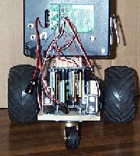
The "Brain" of my fighter is the Basic Stamp I modules from Parallax. These have 8 input/output lines. Two lines are used for the servos, 3 lines are used for the IR vision system which allows the robot to see, one line for the touch sensor shut off switches, and two lines are used for my IR edge detector sensors. The picture below shows two bread boards attached to the inside of the lid via brass clips. The lid in fact is what holds my bot's electronics. This allows me to detach only a few wires and have the ability to take all of my bot's electronics away to work on them. It is more open then placing them inside the case it's self. I would like to point out that in the event my bots should fall backwards they will not land on the Stamp. So even though my Stamps are on the outside of the case they are still protected.
|
|
Pins Used:
|
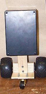
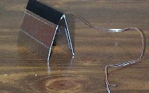
The main sensor on all fighters is the 2" by 2" shut off sensor. I had planned on using a pressure sensor much like the one described for Bolo-Bot under our projects area. You know, where you use two pieces of foil with a piece of anti-static foam in the middle (the type ICs are picked in) with wires connected to the to pieces of aluminum foil. When pressed this would give a reading to a LM339 chip and our robot could cut power to it's motors. Some have suggest that you could just use a contact switch and attach it to a 2" by 2" plate.
But, I wanted to try to make my bot as simple as possible so that even newbies would not be afraid to follow along and build a fighter like mine. So I throw all ideas out the window and cut a 4 1/2" by 2" piece of cardboard from an old box. I bent it in the middle and took some aluminum tape I had and taped both ends, but not the middle of the carboard. Then I took a piece of wire left over from my stereo and taped that with the same tape to the inside of my new "free" contact sensor. If you took foil instead of tape (making sure to leave the middle untapped for contact) it would work just as good. And it would cost nothing! My free sensor is pictured below.
|
|
You can order my free sensor from me for just $19.95, and if you order now I'll throw in a second free contact sensor FREE!! My sensor is picture to the left, some may mock my interest in cheap parts but I follow the law of Ockham's Razor, "It is foolish to do with more what can be done with less." My sensor works very well. |
Motor Shut Off:
This is the circuit for my motor shut off sensor, both switches are wired to the same pin
on the Stamp. This program uses the "Debug" statement so display readings
on your computers monitor. When you press the switch you should see a "1"
when the sensor is not depressed you should see a "0". More advance
programs will follow as examples of what my fighters can do.
|
|
INPUT PIN4 |
IR Navigation Sensor:
Now, I have two very different IR sensor on my fighters. One is a kit from Lynxmotion that sells for $30. I know
that can be a bit high for one sensor, but what I liked was that this IR sensor will work
in direct sun light and has a very good range. I really like the sensor. I
bought two for my big robot Wally but I am using them
for my fighters. I am providing a circuit below of it and the programming example
for testing this. It's not a complex circuit and you can bread board it in a few
minutes. I want to point out that I did not have a Sharp module in my schematic
making program so I stuck it in labeled as Macro. Nevertheless, it is the Sharp
GP1U581Y that you can get from Radio Shack. Now the pins on the Sharp module may not
be labeled exactly, but if you get a data sheet with it you'll know which pins go
where. All the inverters in this circuit are not labeled but they are from one chip,
the 74HC04. This is a very common chip you can find at Radio Shack. D1 and D2
are the Right and Left IR LEDs that you will want flanking your detector module. You
may need to play around with placement. Pointed at a slight angle away from the
module works best for me.
I want to explain that you can use a 9 volt battery as the source and the in circuit 7805 provides a nice clean 5 volts out for the rest of the circuit. All ground are tied together! I used pins 5,6,7 from the stamp for control, you can use any pins you want, just make sure you change the pins in the program so they will match your circuit. You also must have a ground from the Stamp (Vss) to the ground of the circuit. Do not power this circuit from the Stamp's Vss and Vdd power lines; this sensor is too power hunger to do that.
This sensor from Lynxmotion is not the best in the world. One nice feature is that the board returns variable readings so you can know if you how close you are to nearby objects. For straight object detection you don't really need variable readings like this. It also demands more from the your embedded controller because the sensor really does not do anything on it's own. The Basic Stamp is doing all the work. A IRPD kit from Dennis Clark would be a much better investment. Dennis provides you with a programmed PIC chip that does all the work of detection and simply sends a high or low reading to the stamp for left and right detection. Dennis' detector is going to be on my Sagramore2000 fighter because I consider it a better sensor.
|
|
To Test IR Sensor Kit |
This program, if used with the BS I, will display on your computer monitor what value your sensor is sending to the stamp. If all is working you should see 10, 10 from the right and left side. Even though it is one sensor module it gives a right and left reading. So if something is to the right your robot could go left with the proper instructions. The code uses the Debug command to display the sensor readings on your monitor. When something is close to the sensor you'll see 0, 0 and medium range you'll see 5, 5 and if something is blocking just one side of the robot you would see 10, 0 or 0, 10. Does that make sense? You can adjust R2 for sensitivity.
Edge Detection Sensors:
Below is my home made IR sensor for edge detection or line tracking depending on how you
want to use it. Now on my fighter I used the Vss. and Vdd lines because nothing here
is eating power. If you build the IR sensor kit circuit I would suggest you route a
power line from the 5 volts out put from the 7805 to power this and any other circuits you
may whish to use. Q1 is an infrared transistor. I but tape around it and my IR
LED then taped them to each other to form a sensor pair. The range in this set up is
not great, only about 3 to 4 inches. Now I have two IR sensor like this, the other
one uses pins 6 and 7 and pin 1 as the out put. The LM339 is a quad comparator and
so that means for our use here we can make 4 such sensor from one chip.
|
|
INPUT PIN3 |
This program can be used to test most any sensor you can think of. All you need to do is change the 3 to match the pin your sensor is hooked to. The Debug command again displays data on the monitor but this time you will only see a 1 or a 0 for a High or a Low. Now for this circuit pin 3 goes to pin 2 of our 339 chip. But we also have a 10K resistor going from the same pin to the positive. This looks funny at first, but what it does is pull our input pin High. We want this because our LM339 chips give a negative signal on the output on pin 2. So we need to give the Stamp another state to be in. It can't be Low and nothing. So we use the 10K as a "pull up" resistor so the Stamp has a High and a Low state for that input.
I don't have much to say about my servos. I won't go into converting them because you can find plenty of into on that from sites like this. I do want to include here a simple programming for testing your servos. This is for calibrating them. Your run this program then turn the pots on the servos until they stop turning. This is your stop point. You raise it and the servo will go forward, lowing it to reverse. The value 150 is what you change for each servo for control.
'Jason's Quick And Easy Motor Calibration
' ==Variables and Constants
SYMBOL mot_L = b7 ' Left-motor speed.
SYMBOL mot_R = b6 ' Right-motor speed.
SYMBOL Lp = 0 ' Left-motor pin.
SYMBOL Rp = 1 ' Right-motor pin.
'==Main Program Loop
again:
' Repeat forever.
mot_L = 150: mot_R = 150 ' Calibrate motors.
run:
pulsout Lp,mot_L ' Output control pulses.
pulsout Rp,mot_R
pause 15 ' Wait 15ms.
goto again ' Repeate
main loop.
My fighters best defensive weapon will be it's smarts and sensors, I hope anyway! However, as I have tried to pull away from making my fighter like bash em up bots, I almost forgot to give Sir Sagramore a means of hitting the shut off switch on other fighters! I have an arm that can hold different types of weapons, but I fear this may be ineffective. Under my current set up I have no open I/O lines and I need all of the sensor I have now, so I am stuck and see only this options open to me as far as a weapon goes. I would love to hear input on ideas to work around this. Some suggests have been brought to my attention but most of them are evil ones, like make an arm that throws a net over other robots.
The Power:
The servos have 6 volts via a 4 AA battery pack. Each robot also has two
9-volts. One of which will be for the Basic Stamp I and the other for main
circuitry. I would like to point out for anyone wishing to enter the contest that if
you use alkaline or nickel cadmium batteries other than the 9-volt I can recharge them via
a recharger called the Battery Master. I also use Eveready rechargeable batteries
and can charge them even the 9-volts. The Eveready rechargeable batteries are the
ones I plan to use for my robot.
Click here and you'll find all of the complete Fighter Bot programs used on my fighters to date. There is only a very rough program there right now, but it'll be updated as I change the code. I also hope to add little program notes and tips for programming the Basic Stamp along with an explanation of the code so someone not used to programming can learn a little from it.
The Names:
My fighters have names now: Sir Dinadan and Sir Sagramore. You may recognize them
from Camelot. I sort of like the idea of knights of a round table and so if
you would like to name your fighters after other nights here are a few as of yet unused in
the TRCY Robot Fights: Sir Gaban, Sir Lionel, Sir Tristan, Sir Dwight, Sir Clarius,
Arthur, Lancelot, and Mordred. So if you are stuck for a name, why not try one of
these.
Added Thoughts:
I have tried to give enough detailed directions so anyone that wants to build a
fighter like mine can. If I have not done so please feel free to drop me a line at Weyoun7@aol.com, I will welcome all input, feedback and
questions.
I keep learning many things in the design of fighting robots. I have learned two VERY important things from watching my robots fights. The first is give your fighter, no matter if you are entering a robot in the TRCY Robot Fights or in a sumo contest else where, give your fighter as many sensors as possible to detect other robots! IR sensor work just fine for this and I suggest that if you add forward and rear looking IR sensors on your fighter.
The second big thing I learned is NEVER leave your wires sticking out on a fighting robot! Other robots can either on purpose or by accident catch your bot's wires and pull them out! I learned this lesson the hard way. So bolt, tie and tape everything down once your robot is ready for war.
Make your fighter FAST! Speed can make your robot cover the ring better giving the faster fighter the chance to strike first. Fast fighters are harder to catch and harder to stop. Now my old Sagramore robot used 4 AA batteries for servo power, I added a 2 AA pack to the 4 to give the servos a total of 9 volts for power which provides a fast yet smooth pace for my fighters.
Don't forget about the WEAPON! Don't leave out a means for your fighter to engage other robots in battle.
I would like to point out that you do not need to build your robot like mine to enter the TRCY robot fights. I am including all information that is available currently on my robots so that you may build your own like mine or borrow ideas to use in your designs. Making your robot's body like mine would give the robots an even start, but like I said it is not a requirement.
page last updated December 29th 1999
The robots are being built by me, Justin R. Ratliff. Help on my bots has come from all the great members of TRCY!!